|
1 问题概述
本例程演示了在Eye-in-Hand的情况下,当标定板与机器人基准位置保持不变应该如何进行手眼标定。机器人通过标定板来进行手眼标定。在这样的情况下,手眼标定的目的是确定两个未知量:
1)在标定板坐标系下机器人基座的位姿(CalObjInBasePose)
2)在机器人末端工具中心点坐标系下相机的位姿(ToolInCamPose)
从理论上来说,至少需要获取在相机坐标系下的标定物的三个位姿。但实际上,却至少需要使用十个位姿。相应的,在机器人基座坐标系下的机械手夹具的位姿(ToolInBasePose)对于不同的用于标定的图像而言是变化的,原因是因为它是通过移动相机来描述机器人的位姿。标定板的位姿通过固定在机械手末端夹具上的相机拍摄相应的图像来获得。为了获取更好的标定结果,调整相机与标定板的位置以使标定板在图像中呈倾斜的情况是很重要的。相机标定完成后,估计出的转换矩阵将被提取出来,并用于计算在相机坐标系下标定板的位姿。
2 例程解读
2.1 初始化
在这一部分的工作中,需要完成对显示参数的初始化(主要包括2D图像的显示以及3D模型的显示),以及用于标定的模型的初始化(利用已获得的相机内参与标定板参数,同时还可以指定进行标定的方法)
2.1.1 生成图像与数据目录
针对输入的图像进行相应的操作,目的是为了服务2D图像的显示。
* Directories with calibration images and data files
ImageNameStart := '3d_machine_vision/hand_eye/movingcam_calib3cm_' //输入图像的名称
DataNameStart := 'hand_eye/movingcam_' //输入数据的名称
NumImages := 14 //输入图像的数量
read_image (Image, ImageNameStart + '00') //根据名称读取图像
dev_close_window () //关闭图像窗口
get_image_size (Image, Width, Height) //获取图像的大小,单位是像素
dev_open_window (0, 0, Width, Height, 'black', WindowHandle) //根据图像的参数打开相应的窗口
dev_set_line_width (2) //设置图像线宽
dev_set_draw ('margin') //设置图像绘制的方式:边界
dev_display (Image) //显示图像
set_display_font (WindowHandle, 14, 'mono', 'true', 'false') //设置显示的一些参数(这是一个外部函数)
ParamName := ['color_0','color_1','color_2','color_3','color_4','color_5','color_6','alpha_6']
//创建一个字符串数组作为参数名称
ParamValue := ['red','green','blue','red','green','blue','white',0.7] //为这些参数给定相应的值
2.1.2 初始化三维坐标系
这部分主要是为了初始化相应的三维坐标系:一个是以机械手夹具中心点为原点的三维坐标系,另一个是机器人基座的三维坐标系。
* Labels for the visualized 3D object models.
tuple_gen_const (7, '', Labels) //创建一个元数组用于保存Labels
Labels[0] := 'Robot\'s Tool' //声明相应的名称
Labels[3] := 'Robot\'s Base'
Instructions[0] := 'Rotate: Left button' //重新声明Instruction
Instructions[1] := 'Zoom: Shift + left button'
Instructions[2] := 'Move: Ctrl + left button'
* Set size for 3D visualization in [m]
ArrowThickness := 0.005 //初始化箭头线条
ArrowLength := 0.05 //初始化箭头长度
gen_robot_tool_and_base_object_model_3d (ArrowThickness, ArrowLength, OM3DToolOrigin, OM3DBase) //创建机械手与机器人的三维模型
2.1.3 初始化标定模型
这里做的工作主要是初始化一个用于标定的模型CalibDataID。需要通过标定文件,相机初始内参以及用于进行标定的方法进行初始化。
* Load the calibration plate description file.
* Make sure that the file is in the current directory or
* in HALCONROOT/calib, or use an absolute path.
CalTabFile := 'caltab_30mm.descr' //加载标定文件
* Read the initial values for the internal camera parameters
read_cam_par (DataNameStart + 'start_campar.dat', StartCamParam) //获取相机初始内参
* Create the calibration model for the hand eye calibration
* where the calibration object is observed with a camera
create_calib_data ('hand_eye_moving_cam', 1, 1, CalibDataID) //创建一个标定数据对象CalibDataID
* Set the camera type used
set_calib_data_cam_param (CalibDataID, 0, [], StartCamParam) //设置用于标定的相机参数
* Set the calibration object
set_calib_data_calib_object (CalibDataID, 0, CalTabFile) //设置用于标定的标定板参数
* Start the loop over the calibration images
* Set the optimization method to be used
set_calib_data (CalibDataID, 'model', 'general', 'optimization_method', 'nonlinear')
//设置标定所使用的方法
disp_message (WindowHandle, 'The calibration data model was created', 'window', 12, 12, 'black', 'true')
disp_continue_message (WindowHandle, 'black', 'true')
2.2 构建坐标系
2.2.1 构建标定板坐标系
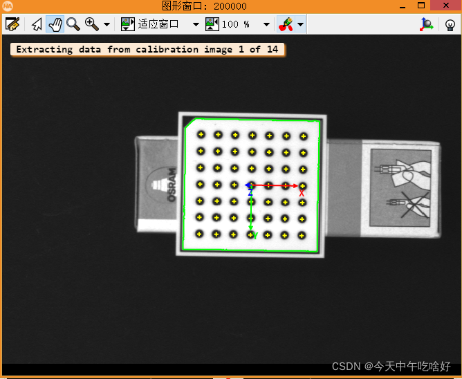
根据之前创建的标定对象CalibDataID在图像中寻找相应的标定板图像,获取标定板的轮廓与其中的角点,并在其中心根据相机内参以及标定板位姿初始化一个标定板坐标系。
dev_open_window (0, Width + 10, Width, Height, 'black', WindowHandleR) *利用窗口句柄新建一个新窗口
set_display_font (WindowHandleR, 14, 'mono', 'true', 'false') *初始化这个新窗口
for I := 0 to NumImages - 1 by 1 *遍历输入的图像
dev_set_window (WindowHandle) *设置当前的窗口
dev_clear_window () *清空当前窗口内容
read_image (Image, ImageNameStart + I$'02d')
dev_display (Image) *读取并显示相应的图片
* Search for the calibration plate, extract the marks and the
* pose of it, and store the results in the calibration data
* The poses are stored in the calibration data model for use by
* the hand eye calibration and do not have to be set explicitly
find_calib_object (Image, CalibDataID, 0, 0, I, [], []) *在输入的图像中根据之前初始化的标定模型,寻找标定板
get_calib_data_observ_contours (Caltab, CalibDataID, 'caltab', 0, 0, I) *提取标定板的轮廓
get_calib_data_observ_points (CalibDataID, 0, 0, I, RCoord, CCoord, Index, PoseForCalibrationPlate) *通过提取标定板中的点,来获取标定板的位姿
* Visualize the extracted calibration marks and the estimated pose (coordinate system)
dev_set_color ('green') *用绿色显示标定板轮廓
dev_display (Image)
dev_display (Caltab)
dev_set_color ('yellow') *用黄色显示角点颜色
disp_cross (WindowHandle, RCoord, CCoord, 6, 0) *显示角点(通过计算行列交点)
dev_set_colored (3)
disp_3d_coord_system (WindowHandle, StartCamParam, PoseForCalibrationPlate, 0.01)
*根据相机的内参和标定板的位姿显示三维坐标系
disp_message (WindowHandle, 'Extracting data from calibration image ' + (I + 1) + ' of ' + NumImages, 'window', 12, 12, 'black', 'true')
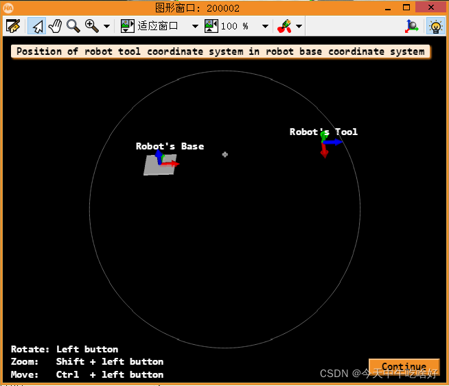
2.2.2 构建机器人基座坐标系与夹具坐标系
根据保存的机器人工具坐标系到机器人基座坐标系下的转换矩阵,将原有的机器人夹具坐标系转换至基座坐标系下,显示这两个坐标系并将转换关系保存在CalibDataID所指向的模型对象中。
* Read pose of tool in robot base coordinates (ToolInBasePose) *读取机械手在机器人基座坐标系下的位姿
read_pose (DataNameStart + 'robot_pose_' + I$'02d' + '.dat', ToolInBasePose)
if (I == 0)
PoseIn := [-0.006,-0.296,12,178,2,270,0]
else
PoseIn := PoseOut
endif
rigid_trans_object_model_3d (OM3DToolOrigin, ToolInBasePose, OM3DTool) *根据机械手在机器人基座坐标系下的转换矩阵,将机械手坐标系转换至基座坐标系下
visualize_object_model_3d (WindowHandleR, [OM3DTool,OM3DBase], [], PoseIn, ParamName, ParamValue, 'Position of robot tool coordinate system in robot base coordinate system', Labels, Instructions, PoseOut) *模型可视化
clear_object_model_3d (OM3DTool) *清除机械手坐标系
* Set the pose tool in robot base coordinates in the calibration data model
set_calib_data (CalibDataID, 'tool', I, 'tool_in_base_pose', ToolInBasePose) *保存机械手坐标系到基座坐标系的转换关系至标定模型CalibDataID中
endfor
dev_set_window (WindowHandleR) *关闭三维视窗
dev_close_window ()
disp_message (WindowHandle, 'All relevant data has been set in the calibration data model', 'window', 12, 12, 'black', 'true')
disp_continue_message (WindowHandle, 'black', 'true')
stop ()
2.3 执行手眼标定
2.3.1 检查用于手眼标定的位姿是否一致
* Check the input poses for consistency
check_hand_eye_calibration_input_poses (CalibDataID, 0.05, 0.005, Warnings) *检查用于进行标定的位姿矩阵是否具有一致性
if (|Warnings| != 0)
* There were problem detected in the input poses. Inspect Warnings and
* remove erroneous poses with remove_calib_data and remove_calib_data_observ.
dev_inspect_ctrl (Warnings)
stop ()
endif *如果检查到位姿矩阵不具备一致性则清空相应位姿
2.3.2 进行手眼标定并保存相应参数
下面开始进行手眼标定,相机的标定已经在手眼标定之前完成。
dev_display (Image)
disp_message (WindowHandle, 'Performing the hand-eye calibration', 'window', 12, 12, 'black', 'true')
calibrate_hand_eye (CalibDataID, Errors) *进行手眼标定
* Query the error of the camera calibration *获取相机标定的误差
get_calib_data (CalibDataID, 'model', 'general', 'camera_calib_error', CamCalibError)
* Query the camera parameters and the poses *获取相机的参数
get_calib_data (CalibDataID, 'camera', 0, 'params', CamParam)
* Get poses computed by the hand eye calibration *获取机械手末端夹具在相机坐标系下的坐标
get_calib_data (CalibDataID, 'camera', 0, 'tool_in_cam_pose', ToolInCamPose)
get_calib_data (CalibDataID, 'calib_obj', 0, 'obj_in_base_pose', CalObjInBasePose)
*计算标定板在基座坐标系下的坐标
* Get the plane in base coordinate system pose by translating the
* CalObjInBasePose by the calibration object's thickness in the
* z-direction.
set_origin_pose (CalObjInBasePose, 0, 0, 0.005, PlaneInBasePose) *将标定板根据其厚度矫正至与base同平面
dev_get_preferences ('suppress_handled_exceptions_dlg', PreferenceValue)
dev_set_preferences ('suppress_handled_exceptions_dlg', 'true') *获取并保存相关参数
try
* Handle situation where user does not have the permission
* to write in the current directory.
*
* Store the camera parameters to file *保存相关参数
write_cam_par (CamParam, DataNameStart + 'final_campar.dat')
* Save the hand eye calibration results to file
write_pose (ToolInCamPose, DataNameStart + 'final_pose_cam_tool.dat')
write_pose (CalObjInBasePose, DataNameStart + 'final_pose_base_calplate.dat')
write_pose (PlaneInBasePose, DataNameStart + 'final_pose_base_plane.dat')
catch (Exception)
* do nothing
endtry
dev_set_preferences ('suppress_handled_exceptions_dlg', PreferenceValue)
2.3.3 显示标定误差
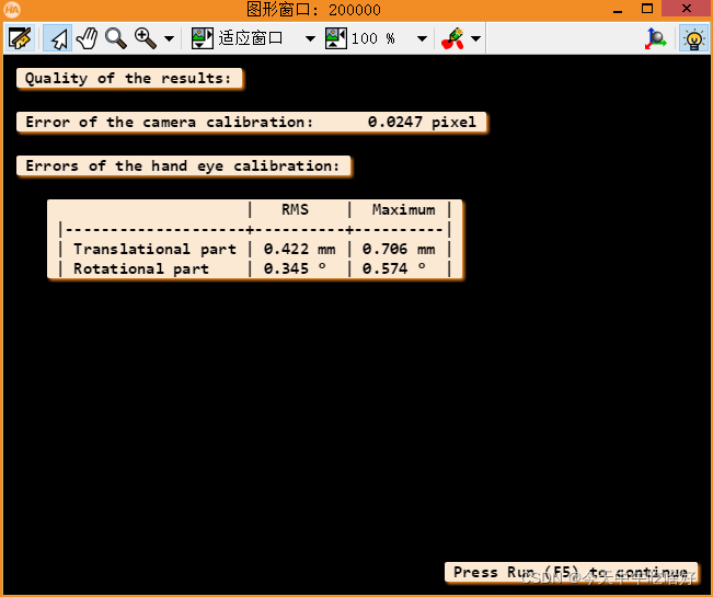
dev_display (Image)
* Display calibration errors
disp_results (WindowHandle, CamCalibError, Errors) *显示手眼标定后的误差与相机误差
disp_continue_message (WindowHandle, 'black', 'true')
stop ()
2.4 显示标定后的三维模型
2.4.1 计算姿态指标和标定对象指标
* For the given camera, get the corresponding pose indices and calibration object indices
query_calib_data_observ_indices (CalibDataID, 'camera', 0, CalibObjIdx, PoseIds)
2.4.2 可视化
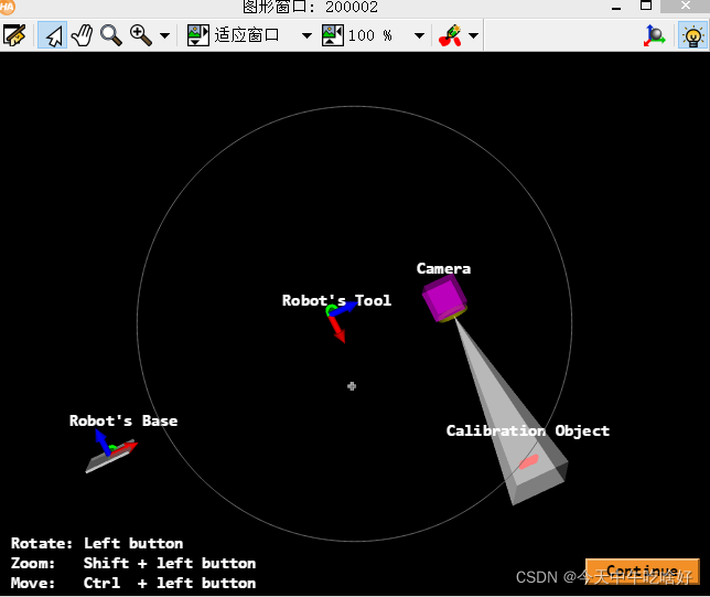
* Compute the pose of the calibration object in the camera coordinate
* system via calibrated poses and the ToolInBasePose and visualize it.
* Set sizes for 3D visualization in [m]
CameraSize := 0.05 *这两个参数是用来初始化相机的
CameraConeLength := 0.3
get_calib_data (CalibDataID, 'calib_obj', 0, 'x', PX) *获取标定块的坐标数据
get_calib_data (CalibDataID, 'calib_obj', 0, 'y', PY)
get_calib_data (CalibDataID, 'calib_obj', 0, 'z', PZ)
gen_object_model_3d_from_points (PX, PY, PZ, OM3DObjectOrig) *根据坐标数据初始化标定块
rigid_trans_object_model_3d (OM3DObjectOrig, CalObjInBasePose, OM3DObject) *根据标定块在基座坐标系下的转换矩阵对标定块进行转换
clear_object_model_3d (OM3DObjectOrig)
dev_open_window (0, Width + 10, Width, Height, 'black', WindowHandleR) *新建一个窗口用于进行三维显示
set_display_font (WindowHandleR, 14, 'mono', 'true', 'false')
ParamName := ['color_0','color_1','color_2','color_3','color_4','color_5','color_6','color_7','alpha_7','color_8','color_9','color_10','alpha_8','alpha_9','alpha_10','point_size']
ParamValue := ['red','red','green','blue','red','green','blue','white',0.7,'magenta','yellow','white',0.5,0.5,0.5,5]
*初始化参数名称与数值
* Labels for the visualized 3D object models.
tuple_gen_const (11, '', Labels) *初始化三维坐标系的坐标轴
Labels[0] := 'Calibration Object'
Labels[1] := 'Robot\'s Tool'
Labels[4] := 'Robot\'s Base'
Labels[8] := 'Camera'
for I := 0 to NumImages - 1 by 1
dev_set_window (WindowHandle)
dev_clear_window ()
read_image (Image, ImageNameStart + I$'02d')
dev_display (Image) *读取相应的图片
* Obtain the pose of the tool in robot base coordinates used in the calibration.
* The index corresponds to the index of the pose of the observation object.
get_calib_data (CalibDataID, 'tool', PoseIds[I], 'tool_in_base_pose', ToolInBasePose)
* Compute the pose of the calibration object relative to the camera
calc_calplate_pose_movingcam (CalObjInBasePose, ToolInCamPose, ToolInBasePose, CalObjInCamPose)
*通过相机参数计算标定块的位姿
* Display the coordinate system
dev_set_colored (3)
disp_3d_coord_system (WindowHandle, CamParam, CalObjInCamPose, 0.01)
Message := 'Using the calibration results to display '
Message[1] := 'the coordinate system in image ' + (I + 1) + ' of ' + NumImages
disp_message (WindowHandle, Message, 'window', 12, 12, 'black', 'true')
gen_camera_and_tool_moving_cam_object_model_3d (ToolInCamPose, ToolInBasePose, CameraSize, CameraConeLength, OM3DToolOrigin, CamParam, OM3DCamera, OM3DTool)
if (I == 0)
PoseIn := [-0.006,-0.296,12,178,2,270,0]
else
PoseIn := PoseOut
endif
visualize_object_model_3d (WindowHandleR, [OM3DObject,OM3DTool,OM3DBase,OM3DCamera], [], PoseIn, ParamName, ParamValue, [], Labels, Instructions, PoseOut)
clear_object_model_3d (OM3DTool)
clear_object_model_3d (OM3DCamera)
endfor
2.5 清除模型并计算相应矩阵
clear_calib_data (CalibDataID)
clear_object_model_3d (OM3DObject)
clear_object_model_3d (OM3DToolOrigin)
clear_object_model_3d (OM3DBase)
dev_set_window (WindowHandleR)
dev_close_window ()
*
* After the hand-eye calibration the computed pose
* ToolInCamPose can be used in robotic grasping applications.
* To grasp an object with the robot, typically, its pose
* with respect to the camera is determined (which
* is simulated here by setting the object's pose to the
* pose of the calibration object)
ObjInCamPose := CalObjInCamPose
* If the tool coordinate system is placed at the gripper
* and a detected object ObjInCamPose shall be grasped
* (here the calibration object),
* the pose of the detected object relative
* to the robot base coordinate system has to be computed.
pose_invert (ToolInCamPose, CamInToolPose)
pose_compose (ToolInBasePose, CamInToolPose, CamInBasePose)
pose_compose (CamInBasePose, ObjInCamPose, ObjInBasePose)
3 思路整理
本Halcon例程的目的是完成 Eye-in-Hand 条件下的手眼标定。以解决  问题来完成手眼标定的角度来看,我们只需要获得机械手夹具到机器人基座坐标系的转换关系 问题来完成手眼标定的角度来看,我们只需要获得机械手夹具到机器人基座坐标系的转换关系  以及相机标定的参数 以及相机标定的参数  即可解决这一手眼标定问题。 即可解决这一手眼标定问题。
在本例程中,已经获得了tool到base的转换关系以及cam的参数。因此,还需要进行的工作就是用  完成摄像机标定,构建相应的三维坐标系并评估评定的结果。 完成摄像机标定,构建相应的三维坐标系并评估评定的结果。
例程的整体流程梳理如下:
1)初始化相应的参数:二维图像输出窗口,三维坐标系的坐标轴与窗口,用于进行手眼标定的对象CalibDataID;
2)根据手眼标定的对象,在输入的图像中寻找相应的标定板,并建立坐标系;
3)创建base与tool的三维坐标系,并根据输入的转换关系信息进行显示;
4)进行手眼标定,输出并保存相关参数;
5)根据标定后的转换关系,创建base、tool、cam与obj的三维坐标系,并进行显示;
6)输出相应的转换关系。
|