| 第十四讲:神州交换机链路聚合配置 | 您所在的位置:网站首页 › 三层业务链怎么做 › 第十四讲:神州交换机链路聚合配置 |
第十四讲:神州交换机链路聚合配置
|
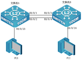
链路聚合(Link Aggregation)又称Trunk,是指将多个物理端口捆绑在一起,成 为一个逻辑端口,以实现出/入流量在各成员端口中的负荷分担,交换机根据用户配置的端口负荷分担策略决定报文从哪一个成员端口发送到对端的交换机。链路聚合在增加链路带宽、实现链路传输弹性和冗余等方面是一项很重要的技术。 实验拓扑如下图所示
设 备 IP Mask 端 口 交换机A 192.168.1.11 255.255.255.0 1-2 port–group 交换机B 192.168.1.12 255.255.255.0 3-4 port–group PC1 192.168.1.101 255.255.255.0 交换机A端口23 PC2 192.168.1.102 255.255.255.0 交换机B端口24 操作步骤: 步骤1:按照图所示,正确连接拓扑结构。 步骤2:为交换机A设置名称和管理地址 switch#config switch(config)#hostname switchA switchA(config)#interface vlan 1 !进入VLAN1接口 switchA(Config-if-Vlan1)#ip address 192.168.1.11 255.255.255.0 !配置VLAN1的IP地址 switchA(Config-if-Vlan1)#no shutdown !开启该端口 switchA(config)#spanning-tree !启用生成树协议 步骤3:为交换机B设置名称和管理地址 switch(config)#hostname switchB !交换机名称为switchB switchB(config)#interface vlan 1 !进入VLAN1接口 switchB(Config-if-Vlan1)#ip address 192.168.1.12 255.255.255.0 !配置VLAN1的IP地址 switchB(Config-if-Vlan1)#no shutdown !开启该端口 switchB(config)#spanning-tree !启用生成树协议 MSTP is starting now,please wait………….. MSTP is enabled successfully. 步骤4:在交换机A上创建port group。 switchA(config)#port–group 1 !创建聚合端口1 步骤5:在交换机A上验证配置。 switchA#show port-group brief !显示port-group 1的摘要信息 Port –group number:1 Number of ports in port-group:2 Maxports in port-channel=8 Number of port-channels:0 Max port-channels:1 在交换机B上创建port group。 switchB(config)#port–group 1 !创建聚合端口 步骤7:在交换机A上手工生成链路聚合组。 switchA(config)#interface ethernet0/0/1-2 switchA(Config-If-Port-Range)#port-group 1 mode on !强制e0/0/1-2端口加入到聚合端口,并设置为on模式 switchA(Config-If-Port-Range)#exit switchA(config)#interface port-channel 1 !进入聚合端口 步骤8:在交换机A上验证配置。 switchA#show vlan VLAN Name Type Media Ports1 default Static ENET Ethernet0/0/3 Ethernet0/0/4 Ethernet0/0/5 Ethernet0/0/6 Ethernet0/0/7 Ethernet0/0/8 Ethernet0/0/9 Ethernet0/0/10 Ethernet0/0/11 Ethernet0/0/12 Ethernet0/0/13 Ethernet0/0/14 Ethernet0/0/15 Ethernet0/0/16 Ethernet0/0/17 Ethernet0/0/18 Ethernet0/0/19 Ethernet0/0/20 Ethernet0/0/21 Ethernet0/0/22 Ethernet0/0/23 Ethernet0/0/24 Port-Channel1 !port-channel1已经存在步骤9:在交换机B上手工生成链路聚合组。 switchB(config)#interface ethernet0/0/3-4 switchB(Config-If-Port-Range)#port-group 1 mode on !强制e0/0/3-4端口加入到聚合端口 switchB(Config-If-Port-Range)#exit switchB(config)#interface port-channel 1 !进入聚合端口 步骤10:在交换机B上验证配置。 switchB#show port-group brief !显示port-group摘要信息 Port-group number:1 Number of ports in port-group:1 Maxports in port-channel=8 Number of port-channels:1 Max port-channels:1 步骤11:在交换机A上实现LACP动态生成链路聚合。 switchA(config)#interface Ethernet 0/0/1-2 switchA(Config-If-Port-Range)#port-group 1 mode active !将e0/0/1-2端口加入到聚合端口,并设置为active模式 switchA(Config-If-Port-Range)#exit switchA(config)#interface port-channel 1 !进入聚合端口 步骤12:在交换机A上验证配置。 switchA#show vlan VLAN Name Type Media Ports 1 default Static ENET Ethernet0/0/3 Ethernet0/0/4 Ethernet0/0/5 Ethernet0/0/6 Ethernet0/0/7 Ethernet0/0/8 Ethernet0/0/9 Ethernet0/0/10 Ethernet0/0/11 Ethernet0/0/12 Ethernet0/0/13 Ethernet0/0/14 Ethernet0/0/15 Ethernet0/0/16 Ethernet0/0/17 Ethernet0/0/18 Ethernet0/0/19 Ethernet0/0/20 Ethernet0/0/21 Ethernet0/0/22 Ethernet0/0/23 Ethernet0/0/24 Port-Channel1 !port-channel1已经存在 步骤13:在交换机B上实现LACP动态生成链路聚合。 switchB(config)#interfce e0/0/3-4 switchB(Config-If-Port-Range)#port-group 1 mode passive !将e0/0/3-4端口加入到聚合端口,并设置为passive模式 switchB(config)#interface port-channel 1 !进入聚合端口 步骤14:在交换机B上验证配置。 switchB#show port-group brief !显示port-group摘要信息 Port-group number:1 Number of ports in port-group:1 Maxports in port-channel=8 Number of port-channels:1 Max port-channels:1 步骤15:使用ping命令验证 交换机A 交换机B 结果 原 因 1~2 3~4 通 链路聚合组连接正确 1~2 3~4 通 拔掉交换机B端口4的网线,仍然可以通(需要点时间),此时用show vlan看看结果,port-channel消失。只有一个端口连接的时候,没有必要再维持一个port-channel了。 1~2 5~6 通 等待一小段时间后,仍然是通的。用show vlan看结果,此时把两台交换的spanning-tree功能禁用,这时候使用第三步和第四步的结果会不同。采用第四步的,将会形成环路。
|
【本文地址】